
Guangzhou WeiLongDa
Electromechanical Equipment Co., Ltd.
Electromechanical Equipment Co., Ltd.
 Hot Line
86-20-36869698
Hot Line


 |


| Quantity: | |
|---|---|
WLD-PCL-T
WLD
Pre-Treatment For Spraying
Spray System Design Description:
The overall spray material is made of 304 stainless steel, which offers strong rust resistance and corrosion resistance.
Base plate: All base-plate connections must be fully welded to ensure structural strength while minimizing the risk of water leakage.
Side panels: The side panels are fabricated by bending sheet material, which not only simplifies installation but also ensures the overall structural rigidity of the spray channel.
Roof panel: The roof panel is made of δ1.0 stainless steel sheet, which reduces the weight of the roof while ensuring the strength of the roof surface; the price is relatively moderate.
Water barrier plate: The design of the water barrier plate effectively reduces the cross-contamination of chemical solutions between different process stages, thereby lowering the amount of chemical solution required and reducing production costs for customers.
Nozzle: Clamp-type spray head; its simple installation method ensures effective spraying and enables rapid replacement.
Pre-treatment process: degreasing → water washing 1 → ceramicization → water washing 2
Water tank: The entire water tank is constructed from welded 304 stainless steel sheets, making it sturdy and reliable with strong rust and corrosion resistance; after the sheets undergo a brushed finish, they achieve an elegant and aesthetically pleasing appearance. A protective film can be applied to shield the sheets from minor scratches, preserving their visual appeal while reducing the risk of impact and scuffing during transport.
The concealed bottom drain design is aesthetically pleasing while ensuring that turbid water is completely discharged when cleaning the water tank, thereby significantly reducing the difficulty and time required for personnel to clean the tank.
Overflow outlet: The overflow outlet is designed primarily to prevent the water level in the tank from becoming too high, thereby avoiding overflow from the tank into the workshop when the water volume exceeds the capacity. This protects the workshop environment and also reduces the workload of personnel.
specifications
Name: Water tank | Specifications: 3000/2000*1220*870 | Quantity: 4 sets |
Material: brushed 304 stainless steel panel |
|
|
Water tank body: δ1.5 304 stainless steel |  | |
Water tank cover: δ1.0 304 stainless steel | ||
Filtration: stainless steel sieve |
|
|
Drainage outlet: bottom-set type | Size: φ75 |
|
Overflow port: φ75 |
|
|
spray
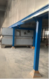
Sprinkler system: L39000 × W1600 × H3900 mm (subject to the final approved design) | ||
Spray framework: 8# square channel, 40×80 square channel, δ1.8 mm |
|
|
Surface treatment: powder coating |
|  |
Base plate: δ1.5 stainless steel 304 |
| |
Side panel: δ1.2 stainless steel 304 |
| |
Roof: δ1.0 304 stainless steel |
| |
Water barrier plate: δ1.0 304 stainless steel |
| |
Drain outlet and inlet/outlet plates: δ1.2 stainless steel 304 |
| |
Imported stairs: patterned panel welding | Quantity: 1 set | |
Pump: 4 sets (vertical submersible pumps) Brand: China | 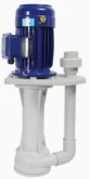 | |
Acid-and alkali-resistant: Yes |
| |
Sprinkler fittings: | ||
Pipe fitting material: PVC |
|
|
Elbows and reducers: PVC material | Internal branch: 1 cun |
|
Spray head: clip-on nozzle (fan-shaped) | Specification: 1 inch | 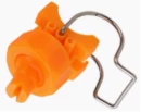 |
Oven
Introduction: The oven employs a bridge-type design, which saves workshop space; it is powered by a gas burner or oil burner (dual-purpose for both preparation and operation). A fan draws air from inside the oven and circulates it through the combustion chamber, thereby raising the internal temperature. This internal circulation heating method significantly improves energy efficiency, while also ensuring uniform oven temperature and increasing the product yield rate.
Exhaust gas collection hood: The exhaust gas collection hood is constructed from galvanized steel sheet and includes one set of inlet and outlet openings for the furnace (excluding the ductwork).
Combustion chamber: The combustion chamber features an inner liner made of high-temperature-resistant stainless steel, with a 150 mm thick insulation layer that provides exceptional thermal insulation while ensuring long-term durability. The image above is
for reference only.


Drying Oven Appendix
Drying oven: L = 22 m; temperature: approximately 120–140 °C; not adjustable Drying oven: L = 22 m; temperature: approximately 120–140 °C; not adjustable | ||
Insulation board: 100 mm rock wool board | Inner layer: δ0.8 galvanized sheet; outer layer: δ0.8 colored sheet; bulk density: 100 kg/m³ | |
Heating: Heat transfer during curing |
|
|
Chassis: 10# galvanized square tubing | Surface treatment: powder coating |
|
Edge banding: δ1.5 galvanized sheet bending | Surface treatment: powder coating |
|
Inside the cotton board joint: aluminum silicate | High-temperature glass sealant sealing |
|
Note: The drying oven does not have a heating device; heat transfer from the curing oven causes the temperature to rise. The temperature is uncontrolled and remains at approximately 140 °C.
Appendix: Curing Furnace
Curing furnace: L = 22 m; temperature: 0–200 °C, adjustable Curing furnace: L = 22 m; temperature: 0–200 °C, adjustable | ||
Combustor: Lioro (Italy), 300,000 kcal | ||
Insulation board: 100 mm rock wool board | Inner layer: δ0.8 galvanized sheet; outer layer: δ0.8 colored sheet; bulk density: 100 kg/m³ | |
Heating: Hot air circulation | Circulation fan: 4-72-6A | Power: 7.5 kW |
Combustion chamber: inner liner made of δ1.5 304 stainless steel | Insulation layer: 150 mm thick |
|
Combustion chamber: 1 set | 3.0t stainless steel sheet |
|
Air duct: δ1.2 galvanized sheet bending |
|
|
Return air duct: δ1.2 galvanized sheet bending | Insulation padding, 50 mm cotton board frame |
|
Chassis: 10# galvanized square tubing | Surface treatment: powder coating |
|
Edge banding: δ2.0 galvanized sheet bending | Surface treatment: powder coating |
|
Inside the cotton board joint: aluminum silicate | High-temperature glass sealant sealing |
|
Exhaust gas collection hood | δ1.2 Galvanized sheet bending (excluding air ducts) |
|
Note: The waste gas emitted by the powder curing furnace is the responsibility of the customer; this equipment does not include a waste gas and wastewater treatment system.
PP Board Large Cyclone Powder Room
Introduction and Design Features
Efficient and rapid color switching;
Continuous automatic cleaning at the bottom of the spray chamber;
The spray chamber base integrates a gas storage pipeline;
During the cleaning process, there is no need to enter the spray chamber;
Segmented bottom cleaning, with solenoid valve control for dual-channel output;
Extraction configurations: flat-bottom sequential air knives, central-bottom extraction, and dedicated extraction slots at the hand-cleaning platform;
The automatic base air cleaning system minimizes the amount of powder remaining in the process flow, thereby enhancing system efficiency;
The verification single cyclone chamber is connected to the powder spraying room piping, while the exhaust duct equipped with a cleaning door reduces the risk of powder contamination;
The air knife uses a small amount of compressed air to generate a continuous curtain-like airflow; it delivers high airflow intensity, consumes less energy, and offers higher efficiency;
The air extraction and distribution system ensures uniform wind speed distribution throughout the bottom air extraction channel, thereby maximizing the recovery of over-sprayed powder and minimizing powder accumulation on the bottom plate;
The gas knife can be subjected to pulse-based reverse blowing, which blows the powder accumulated at the bottom of the powder spraying chamber into the central recovery trough for reuse, thereby maximizing powder utilization and minimizing color-change time;
The air knife operates on the Coanda effect: compressed air is used to generate airflow through a specially designed air chamber, which can divert 20–30 times the volume of ambient air, thereby effectively reducing the consumption of compressed air.
Attached Table for Powder Coating Room
Powder coating room: L6500 × W2200 × H3300 mm; subject to the final approved design | ||
Overall Building Panel Material: PP Board | Screen protector application | |
PP panels: wall panels with thicknesses of 10 mm, 6 mm, and 12 mm, fabricated by assembly and welding of engineering plastics | ||
Powder room base: PP board material | Automatic flap design | 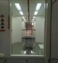 |
Automatic cleaning device | air knife | |
Import/Export Gate | One set each | |
Artificial position | Install platforms on both the import and export sides | |
Fit muzzle | 5 slots per face (1 slot reserved) | |
lighting:LED |
| |
Recycling system: large cyclone, secondary recovery | ||
Secondary Recovery: Quantity: 1 set |
   | |
Filter element: membrane-coated filter element | Quantity: 24 units/12 groups | |
Fan: Type A | Power: 37 kW | |
Big Whirlwind – Quantity: 1 set | ||
Diameter: 1300 mm; Height: 5650 mm | Configuration: Bottom recovery hopper | |
Powder Supply Center | ||
Cabinet material: 2.5 t steel sheet | Powder coating treatment | |
Powder bins: 2 sets | PP board (1 spare set) | |
Display panel: Touch screen |
| |
Nozzle cleaning function: high-pressure air | Vibrating Screen: Configuration | |
Ductwork: equipped with elbows, flanges, and reducers (powder-coated finish) | ||
Delivery System
The conveying equipment primarily consists of an electric drive unit, a counterweight tensioning mechanism, chains, tracks, curved tracks, telescopic tracks, inspection tracks, supports, an electrical control system, and an automatic overload protection device, among other components.
A Type 250 heavy-duty suspended conveying chain is used, with a single-point lifting capacity of 50 kg; one set of an electric drive unit (Vmax ≈ 0–3 m/min) is installed. The tensioning device is equipped with a displacement-limit protection switch, ensuring smooth operation of the chain throughout the entire line. Emergency stop switches are installed along the entire working area, and the drive system is provided with dual mechanical and electrical safety protection;
Chain rail support frame: constructed from 100×100 mm carbon steel square tubing, finished with spray painting.
Areas subject to significant wear: elbows, lifting points, track elbows, and the track assembly at lifting points shall undergo carburizing treatment to increase hardness in these areas, thereby enhancing wear resistance and extending service life.
Transport Schedule
order number | project | specifications | quantity | remarks |
1 | track | QXT-250 | Approximately 230 m | Fit the track sheet |
2 | chain | QXT-250 | Approximately 230 m | Minimum spacing: 250 mm |
3 | Elbow/Lift Assembly | QXT-250 | Formula 1 | carbonization |
4 | actuating device | QXT-250 | 1 set | With safety device |
5 | Tensioning device | QXT-250 | 1 set | Heavy hammer type |
6 | Oil collection plate | 250# | Approximately 920 tablets | galvanized sheet |
7 | Automatic fuel dispenser | 250# | 1 set | Three-point type |
8 | Track posts | 10# Square Tube | 6 m per strand | Painting treatment |

Automatic Powder Spraying Line
1 | Pre-Treatment For Spray Application (L=39m, Spray Type) | 1 Set |
| Dimensions: L×W×H = 39×1.6×3.4 m (subject to the final approved design) |
|
| Structure panels: bottom panel 1.5 t, side panels 1.2 t, top panel 1.0 t; 304 stainless steel sheets |
|
| Water tank: 1.5 t, made of 304 stainless steel | 4 sets |
| Pump: Vertical submersible pump | 4 units |
| Spray pipe: PVC material |
|
| Spray head: clip-on type (fan-shaped) |
|
| Framework: 8# square tube |
|
2 | Heat Transfer In The Drying Oven (L=22 M) And Curing Oven | 1 Set |
| Wall panel: 100 mm thick rock wool sandwich panel |
|
| Frame: 10# galvanized square tubing, powder-coated |
|
| Track installation: hanger |
|
| Furnace partition: 1.2 t galvanized sheet |
|
3 | Curing Furnace (L=22m), Temperature Adjustable | 1 Set |
| Wall panel: 125 mm thick rock wool sandwich panel |
|
| Combustor: 300,000 kcal for the Rialu |
|
| Stainless steel electric heating element: approximately 200 kW |
|
| Combustion chamber: 150 mm thick insulation layer containing a stainless steel inner liner |
|
| Frame: 10# square tubing, powder-coated |
|
| Supply/return air duct: galvanized sheet, 1.2 t |
|
| Exhaust gas collection hood: 1 unit |
|
4 | Powder Spraying Room (Large Cyclone Type) | 1 Set |
| Powder room material: PP board |
|
| Hand-repair platform: 2 sets |
|
| Workpiece rotation device: 1 set |
|
| Lighting: LED lamps |
|
| Large Whirlpool: φ1300 |
|
| Secondary recovery: 37 kW (12 filter cartridges) |
|
| Powder supply center: powder hopper, brush cleaning device, vibrating screen |
|
| Automatic reciprocating lift: 2 units (travel: 1.5 m) |
|
6 | Railway Conveying | 1 Set |
| Track: QXT-250, approximately 230 m |
|
| Chain: QXT-250, approximately 230 m |
|
| Track posts: 10# square tubing |
|
| Oil drain pan: galvanized sheet |
|
| Bolts, nuts, tensile specimens, and other small components |
|
| Tensioning and drive: 2 sets each |
|
| Automatic fuel dispenser: 1 unit |
|
|
|
|
7 | Electrical Control System (Including Cables) | 1 Set |
8 | Spray Gun |
|
| Automatic powder spraying gun: includes control cabinet, powder pump, controller, etc. | 6 sets |
| Manual spray gun: includes powder container, powder pump, controller, etc. | 2 sets |
| Other: automatic powder gun hopper, powder screening machine, powder gun cabinet | 1 set |

